


When deploying any tracking system, the number one question asked is always about the RFID read range. It is the most critical metric for success, yet it is also the most misunderstood. Datasheet range rarely equals real-world range. The actual distance you can achieve depends on a complex interplay of hardware, environment, and physics. In this post, we will explore the nine critical factors that determine your true read distance, helping you avoid common pitfalls and optimize your system.
1. RFID Frequency
The fundamental operating frequency of your system is the baseline for your expected distance. Different frequencies have different wavelengths and energy transfer characteristics, which dictate how far the signal can travel effectively.

- Low Frequency (LF – 125 kHz): These systems operate at very short distances, typically at the centimeter level. They are excellent for access control or animal tracking where close proximity is guaranteed.
- High Frequency (HF/NFC – 13.56 MHz): HF systems offer slightly more distance, usually up to 10 to 30 centimeters. They are widely used for secure payments, ticketing, and library systems.
- Ultra-High Frequency (UHF – 860–960 MHz): UHF is the standard for supply chain and inventory management because it can reach several meters. The shorter wavelength allows for efficient energy transfer over greater distances, making it ideal for reading multiple items simultaneously.
2. RFID Tag Antenna Design (Most Ignored Factor)

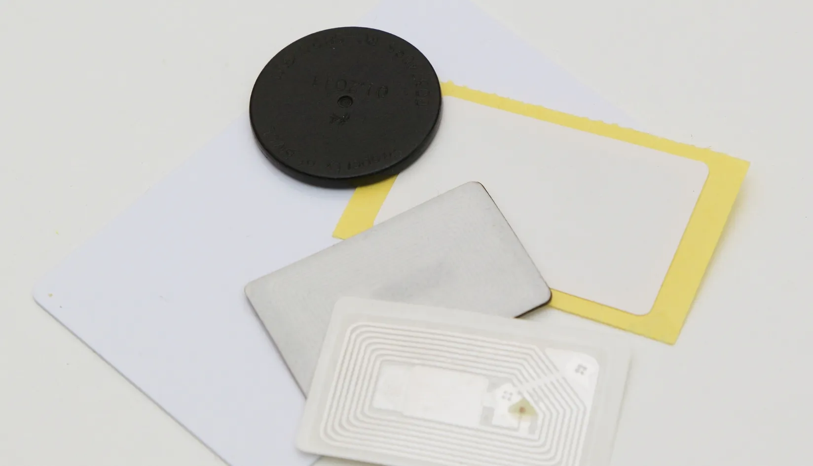
While many focus on the reader, the tag’s antenna design is arguably the most ignored factor influencing your RFID read range. The physical size and structure of the antenna directly correlate with how much energy it can harvest from the reader.
- Larger antennas generally enable longer range
- Cheap, tiny labels sacrifice distance for cost
- Specialized on-metal structures add spacing and tuning layers
- Antenna gain and tuning determine how efficiently energy is harvested
Two tags using the same chip can perform dramatically differently due solely to antenna design.
3. Reader Power Output and Regulatory Limits
The power emitted by your reader is the engine driving the system. Higher power output generally equates to a longer RFID read range, but you cannot simply turn the dial up to maximum without considering regulations.

Readers typically operate at power levels up to 30 dBm (1 Watt). However, lower power settings are often used to prevent interference between adjacent read zones. More importantly, regional regulatory bodies strictly limit maximum power output. The FCC in North America and ETSI in Europe have different rules regarding power and frequency hopping. Because of these varying global regulations, manufacturers often ship readers with conservative default settings. To maximize your distance, you must ensure your reader is configured to the maximum legal power limit for your specific region.
4. Reader Antenna Type and Gain
Just as the tag’s antenna is vital, the reader’s antenna plays a massive role in shaping the RF field. The type of antenna and its gain (measured in dBi) determine how the energy is focused.
- Gain (dBi): higher gain focuses energy farther
- Linear polarization: longer range but sensitive to tag angle
- Circular polarization: shorter peak range but more forgiving
- Portal/gate arrays: create coverage zones instead of beams
Choosing the wrong antenna type is a common reason for disappointing performance.
5. Tag Orientation and Polarization Mismatch

Even with the best hardware, how the tag is physically oriented relative to the reader antenna can drastically alter the RFID read range. This is known as polarization mismatch.
If you are using a linear polarized reader antenna, the tag’s antenna must be aligned parallel to it. Turning the tag 90 degrees can completely kill the read range, rendering the tag invisible to the system.
This is a common issue in real-world applications like warehouse inventory or vehicle access control, where items or vehicles may not always approach the reader at the perfect angle. To combat this, system designers often use circular polarized reader antennas, which are more forgiving of tag orientation, though they do sacrifice a small amount of maximum distance to achieve this flexibility.
6. Environmental Interference (Metal, Water, Human Body)
The environment where your system operates is often the biggest enemy of a long RFID read range. RF signals do not travel through all materials equally, and some materials actively destroy the signal.

- Metal reflects and detunes antennas
- Water and liquids absorb UHF energy
- Human bodies (mostly water) attenuate signals
This is precisely why on-metal tags and spacer designs exist. A standard label that reads 8 m in air may drop to 1 m on a metal surface.
7. Tag Placement Location
Where you place the tag on the item is just as important as the tag itself. Poor placement can negate all other optimizations.
Placing a tag deep inside a box of dense materials will severely limit the signal’s ability to reach the reader. Similarly, placing a tag near the edge of a metal container might cause unpredictable reflections. The ideal placement is usually on the outside of the packaging, facing outward, with a clear line of sight to the reader antenna. In complex scenarios, such as tracking IT assets in a server rack, finding the optimal placement location often requires extensive trial and error to ensure the tag is not shadowed by surrounding metal components.
8. Real-World Noise and Multi-Path Reflection
Laboratory tests always look perfect because they occur in controlled, sterile environments. The real world is noisy and full of obstacles that create multi-path reflections.
In a typical warehouse, RF signals bounce off metal racks, concrete floors, and moving forklifts. This bouncing can cause the signal to arrive at the reader from multiple paths at slightly different times, leading to phase cancellation and dead spots. This multi-path effect can cause a tag to be read perfectly at three meters, become invisible at four meters, and then read perfectly again at five meters. Understanding and mitigating this real-world noise through careful antenna placement and shielding is essential for a reliable system.

9. Tag Chip Sensitivity
While everyone looks at the antenna, the sensitivity of the microchip inside the tag is a hidden specification that heavily influences the RFID read range.
- Typical values: −18 dBm to −22 dBm
- A 3–4 dB improvement can noticeably extend range
- Often overlooked in favor of memory size or price
In long-range designs, this specification matters more than most people realize.
10. Practical Table: What to Adjust If Your Read Range Is Too Short
| Problem | Likely Cause | Fix |
| Reads only at 1 m | Polarization mismatch | Change to a circular polarized antenna |
| Works in air, fails on metal | Tag detuning | Use a specialized on-metal tag |
| Inconsistent reads | Orientation issue | Use circular antenna or adjust tag placement |
| Shorter than datasheet | Low reader power | Increase dBm to maximum legal limit |
11. Conclusion
Ultimately, achieving the desired RFID read range is a system-level result, not just a single specification on a tag’s datasheet. It requires a holistic approach that balances frequency, hardware selection, environmental factors, and physical placement. By understanding these nine critical factors, you can move beyond theoretical datasheet numbers and design a robust, reliable tracking system.
RFIDTag provides high-quality RFID tags and readers to meet your business needs. Visit our website to explore the right solution for your project.
Recommended Product

Concrete Alien Higgs® 9 PPS RFID Tag | 46.5×31.5 mm
The Alien Higgs® 9 Concrete RFID Tag uses durable PPS housing for outstanding heat, impact and corrosion resistance. Ideal for embedding into concrete structures, this UHF tag provides long-range performance and ensures accurate tracking in demanding construction and civil engineering projects.



 EN
 ES
 JA